The FrSky R9 Mini is a FrSky receiver endowed with the features of the previous R9 receivers
FrSky R9 mini pinout. In this article we are going to check the FrSky R9 mini pinout, with a detailed explanation about how to use each pad, and for what porpoises. But first, let's see a small overview.
The FrSky R9 Mini is a receiver endowed with the features of the previous R9 FrSky receiver in a compact and lightweight design, but also it has an improved super low latency, and it also supports the redundancy function. In contrast to some previous versions of the R9 receiver, now the antennas come with an Ipex connector. Having said that, now let's go to the FrSky receiver R9 mini pinout.
FrSky R9 mini pinout
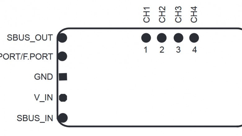
The FrSky R9 mini pinout is very simple, but some pads can cause misunderstandings, for this reason we are going to check every pad, starting with the ones that have a simple use up to the ones that is use is more complex. In the next diagram is represented the FrSky R9 mini pinout.
The GND pad: The first pad of the FrSky R9 mini pinout we are checking is the GND pad. This pad has to be connected to a GND pad, the negative, of the source from where it is being powered, it is usually recommended to find a voltage regulator in the flight controller and connect both GND pads together.
The V_IN pad: The second pad of the FrSky R9 mini pinout we are checking is the V_IN pad. This pad is a voltage input used to power the receiver, it can take from 3,5V up to 10V. Normally flight controllers have a 3.3V and a 5V regulator and even some have a 9V regulator. Although there are some receivers from other brands that only work on 3.3V, this is not the case for most receivers which normally work with a 5V output, so you might prefer to connect this pad to a 5V output.
CH1, CH2, CH3, CH4: This are PWM analog outputs, each channel corresponds to the pad with its number written. For this reason, this receiver can be used also in models that doesn’t require any type of processed signal.
SBUS_OUT: In order to know what this pad is for, we first have to define what SBUS is.
SBUS is the digital communication protocol used in this receiver. It is used as the communication technology that sends the information of the signals received from the controller, that are transmitted to the flight controller, and which is sent digitally. It supports to transmit up to 16 channels per receiver with low latency compared to other protocols, around 55ms less than CPPM and PWM.
As SBUS is a digital communication protocol, all the information can be sent by one cable which can send as many signals as channels have the transmitter. This is quite beneficial to the user comparing it to PWM, which needs a dedicated output for each channel.
After that being said, now we can see what this pad is for. As the name suggests, this pad is used to output the SBUS protocol to the flight controller so that it can process the information and send it to the ESC’s. This pad has to be connected to the RX pad of an UART from a F3 or F7 flight controllers. As this receiver doesn’t have an official uninverted SBUS output, for F4 users is mandatory to connect the SBUS signal to a dedicated RX pad for SBUS.
In addition to this, you have to set up the SBUS protocol in the flight controller. As an example, in Betaflight on the ports tab, you have to select the UART where you have solder the SBUS cable, but also you have to set the protocol used in the configuration tab.
SBUS_IN: The SBUS in pad is made for a specific porpoise, the redundancy function. It is an interesting feature that will require a redundant receiver to be paired with another receiver so that one will act as a backup to the other one in case of failure. For example, if the master receiver goes into failsafe because of low signal, the output signal from the slave receiver will be used until the master receiver exits the failsafe mode.
In order to set this function working, the slave receiver SBUS out pad, must be connected to the SBUS in of the master receiver so that this one can output the signal of the backup receiver by its SBUS out pad in the case that this master receiver fails.
S.PORT: The last pad of the FrSky receiver R9 mini pinout we are checking is the S.PORT pad. This pad is made for the S.Port or F.Port protocols. It has to be connected to the TX pad of a free UART and it is mainly supported by F3 and F7 flight controllers, and it also needs to be set up in the flight controller. As there isn’t any uninverted S.Port output, most F4 flight controllers won’t be compatible with S.Port and F.Port in this receiver.
The S.Port or Smart Port is a telemetry protocol used by FrSky which allows you to get the telemetry information of the model such as battery level, RC signal strength, etc. In contrast, F.Port is a protocol capable of all the features from S.Port and SBUS, all in the same wire, but the receiver will require a firmware update with the F.Port protocol.